In this tutorial it will be demonstrated how to solve a 5-axis toolpath using a stationary tool and a small MOTOMAN SV3 robot. Such a setup could for example consist of a stationary 3D printing head where the robot holds the table on which the part will be printed.
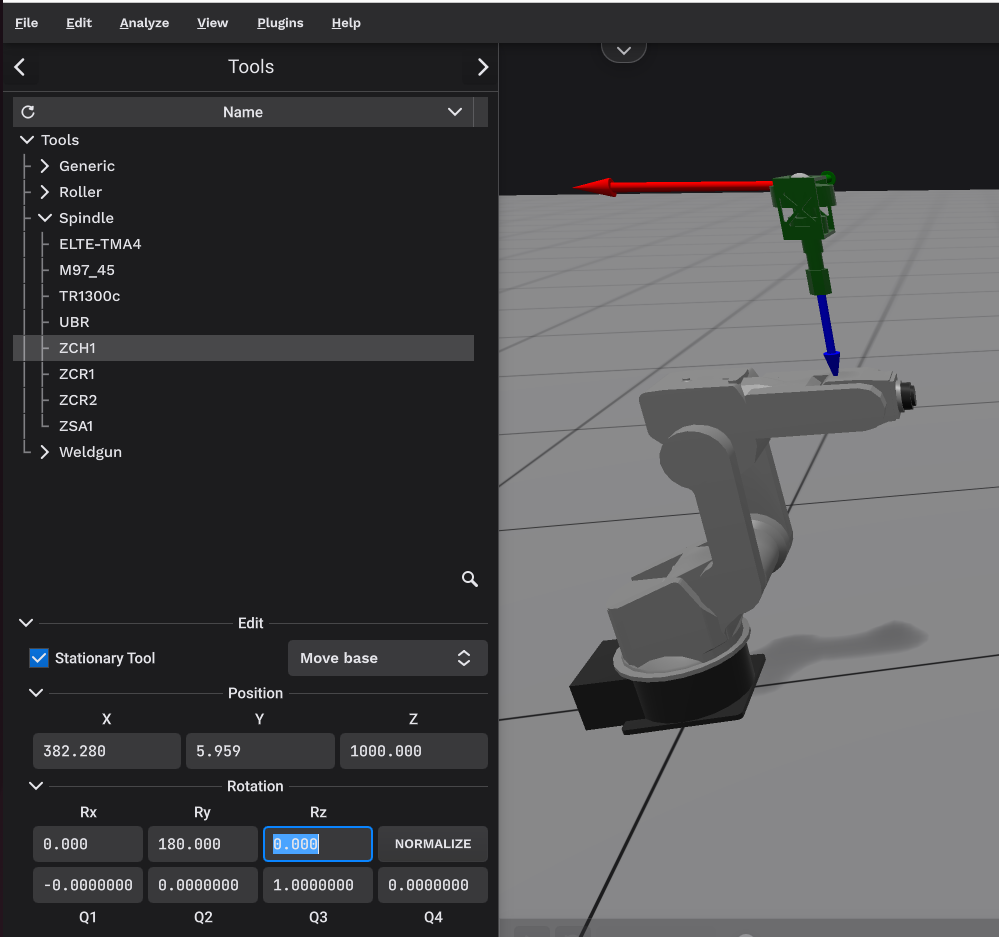
In IRBCAM select File - New - Project Wizard and Confirm followed by Next and no linear track. Select the MOTOMAN SV3 robot followed by Next. Select the Spindle-ZCH1 to represent the print head. Click on Edit near the bottom of the screen followed by the check-box called Stationary Tool. Select “Edit Move base”. Enter the stationary tool base positions: X=382.28, Y=5.959 and Z=1000 and rotation RY=180 as shown in the screenshot below.
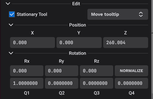
Change the drop-down menu from “Move Base” to “Move Tooltip” and enter Z=260.004 as shown below:
The final location of the stationary tool as seen by the robot will be: X=328.28, Y=5.959 and Z=1000-260.004=739.996. The stationary tooltip location is illustrated by the red-green-blue coordinate system just above the robot in the first screenshot.
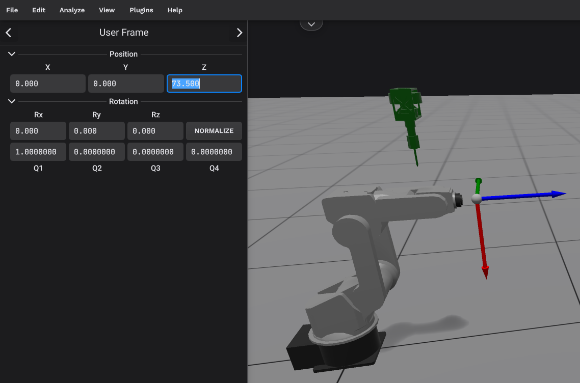
A Rotary table is incompatible with a stationary tool so just click on Next. The SV3 userframe in this case will be attached to the robot’s wrist flange. The tooldata is in this example chosen to be Z=73.5 as shown in the screenshot below.
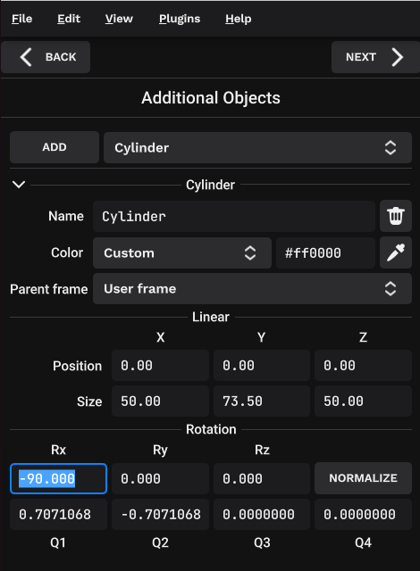
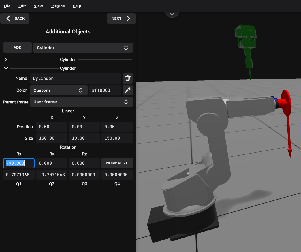
Click on Next. Two Additional Objects (Cylinders) will be created to visualize the table held by the robot. Select Cylinder - Add. Select Parent Frame = User Frame. Set the color to Red. Size: 50, 73.5, 50 and RX=-90 as shown in the screenshot below:
Add a second Additional Object - Cylinder with the same settings, except for Size: 150, 10, 150. The table mounted on the robot’s wrist flange is now shown in red color in the screenshot below.
Click Next and Save your station.
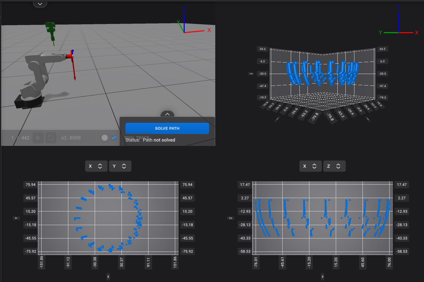
Next, select File - Import Path and select the file named PathRBtool.apt attached to this tutorial. Select View - Combination View to have a look at the imported toolpath in different views as seen in the screenshot below.
Since the toolpath in this example has negative Z-values, do the following:
Edit - Object Frame and rotate by RX=180 degrees
to make sure that the part will be printed on top of the table and not underneath.
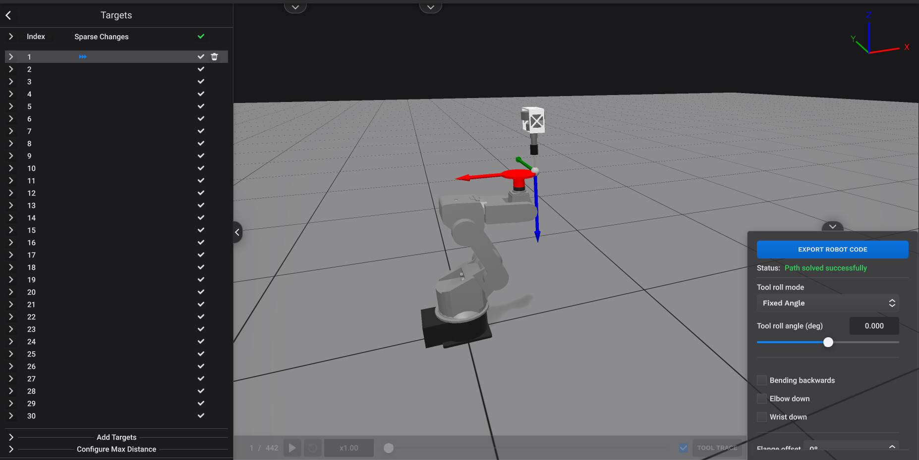
Go back to View - Station. Select Edit - Targets and select target number 1. In the bottom right corner of the screen click on the arrow up above Solve Path to expand the options. Select Tool Roll Mode = Fixed Angle, Initial Tool Roll Angle = 0 (deg). With these settings the entire path should be solved, see the screenshot below:
Deselect Target 1, turn the Tool Trace on with color white. Set the simulation speedup to 5 and press play. The simulation in IRBCAM should be the same as the video below.
PathRBtool.zip (12.5 KB)