It is possible to include user-defined tools in IRBCAM. The first step is to create a 3D drawing of your tool and the adapter to be mounted on the robot flange in your favourite CAD program. A list of file formats that can be imported is found in our FAQ.
When exporting the tool, the coordinate system of the exported file should be as follows.
- The origin (0,0,0) should be at the centre of the mounting flange
- The CAD file should be positioned as shown in the picture below. The mounting flange should be on the floor.
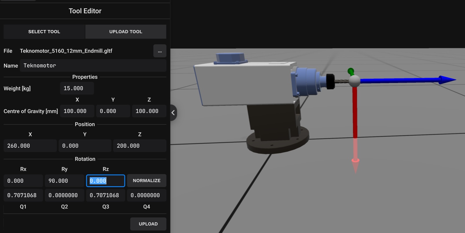
The name of the tool can be modified. In this case the name is set to Teknomotor. Enter the weight of the tool and the centre of gravity (mm). In this example the weight is set to 15kg and the centre of gravity to X=100, Y=0 and Z=100 mm.
The red, blue and green vectors represent the local tool X, Y and Z coordinate directions. This local frame should be located at the tip of the tool. In this case the tip of the tool is located at X=260, Y=0 and Z=200 mm. In IRBCAM the local tool Z-axis (the blue vector in the picture below) should be parallel with the physical tool. This can be achieved by rotating the local tool frame 90 degrees about the Y-axis (the green vector), or Ry=90 as seen in the picture below.
Finally, click on UPLOAD to upload your tool CAD file with the associated tooldata properties.
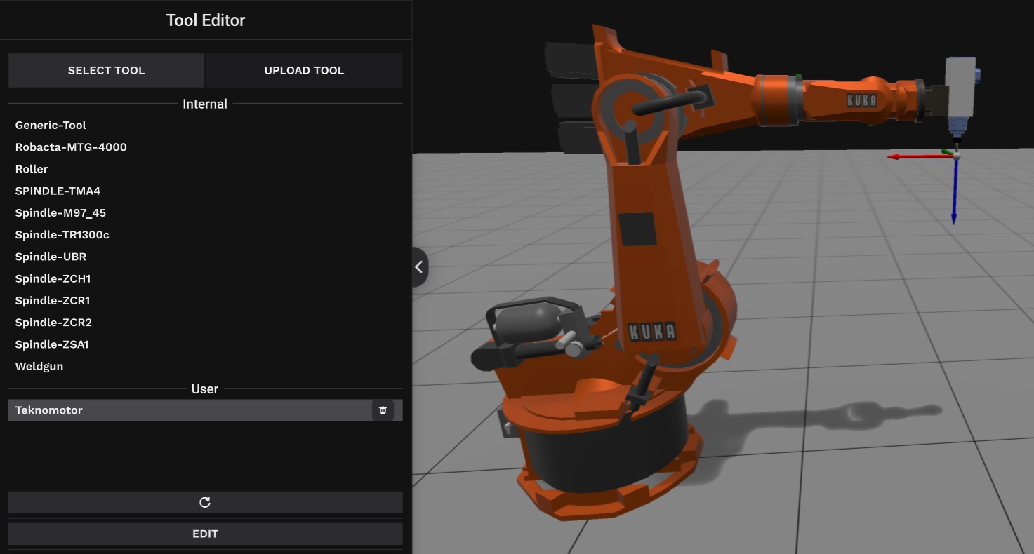
The picture below shows the user-defined tool when connected to a robot. If the CAD file is positioned correctly and the tooldata is entered as described, no further editing of the tool parameters are necessary when the tool is connected to the robot. The picture belows shows the standard tools in IRBCAM (Internal) with the user-defined tool below (User).